Welcome to the GE XL44 manual! This guide provides essential information for safe installation, operation, and maintenance of your range. It covers key features, safety precautions, and troubleshooting tips to ensure optimal performance and longevity of your appliance.
1.1 Overview of the GE XL44 Range
The GE XL44 range is a high-quality gas range designed for efficient cooking. It features electric ignition, anti-tip devices, and models with Standard-Clean or Continuous-Clean capabilities. The range offers a spacious oven and burners for versatile cooking options. Available in various configurations, it suits different kitchen layouts. This manual provides detailed instructions for installation, operation, and maintenance. Key components include durable construction, user-friendly controls, and advanced safety features. Whether you’re a novice or an experienced cook, the GE XL44 ensures reliable performance and ease of use, making it a practical choice for home cooking needs.
1.2 Importance of Reading the Manual
Reading the GE XL44 manual is essential for safe and effective use of your range. It provides critical information on installation, operation, and maintenance, ensuring optimal performance. The manual outlines safety precautions, such as proper electric ignition usage and anti-tip device installation, to prevent accidents. It also guides you through troubleshooting common issues and understanding error codes. By following the manual, you can avoid costly repairs and extend the appliance’s lifespan. Familiarizing yourself with the content helps you utilize all features confidently and efficiently. Always refer to the manual before attempting any maintenance or repairs to ensure everything is done correctly and safely.
Safety Precautions
Adhering to safety guidelines is crucial for safe operation. Proper installation, electric ignition precautions, and anti-tip device use prevent accidents. Follow manual instructions carefully to ensure safety and efficiency.
2.1 General Safety Guidelines
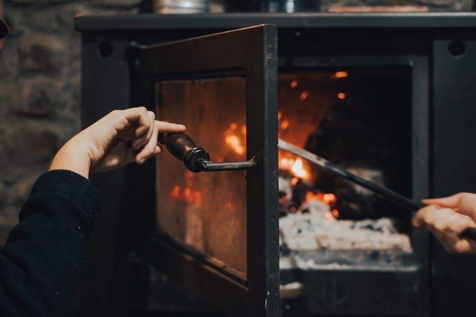
Always read the GE XL44 manual thoroughly before using your range. Ensure proper ventilation to avoid gas fumes accumulation. Keep children away from the appliance while in operation. Never use the range near flammable materials or leave cooking unattended. Avoid wearing loose clothing that could catch fire; Use oven mitts to handle hot surfaces. Regularly inspect burners and igniters for damage. Never attempt repairs without disconnecting power. Follow all safety guidelines to prevent accidents and ensure efficient performance. Proper installation and maintenance are crucial for safe operation.
Remember, safety precautions are non-negotiable for protecting yourself and your home.
2.2 Electric Ignition Safety
For the GE XL44 range, ensure the electric ignition system is installed and maintained correctly to prevent hazards. Avoid modifying or tampering with the ignition components, as this can lead to malfunctions. Keep the area around the burners clear of flammable materials. Always follow the manual’s instructions for lighting burners and using the oven. If you notice irregular ignition or clicking sounds, disconnect power and contact a professional. Never attempt to repair the ignition system yourself. Proper care ensures safe and reliable operation of your range’s electric ignition features.
Regular checks can prevent potential fire risks.
2.3 Anti-Tip Device Installation
The anti-tip device is a critical safety feature of the GE XL44 range. Proper installation ensures the range remains stable and prevents tipping hazards. Follow the manual’s instructions to secure the device to the floor or wall. Tighten all screws firmly to prevent movement. After installation, test the range’s stability by gently pulling it forward; it should not tip. If unsure, consult a professional. Regular checks of the anti-tip device are essential for continued safety. Detailed installation steps and diagrams can be found in the GE XL44 manual. Always prioritize safety to protect your family and home.
2.4 Venting Requirements
Proper venting is essential for safe and efficient operation of the GE XL44 range. Ensure your range is installed with a venting system that meets local building codes and the manufacturer’s specifications. Use approved venting materials, such as stainless steel or galvanized ducts, to prevent gas leaks and ensure proper airflow. The venting system should be installed by a qualified professional to maintain safety and efficiency. Regularly inspect the venting system for blockages or damage. Proper venting prevents carbon monoxide buildup and maintains optimal performance. Refer to the GE XL44 manual for detailed venting requirements and guidelines.

Parts and Accessories
The GE XL44 range includes essential components like burners, ignition systems, and oven racks. Accessories such as knobs, drip pans, and griddles are available for enhanced functionality. Always use genuine GE parts for safety and compatibility. Refer to the GE XL44 manual for a detailed parts list and guidelines for replacement. Proper maintenance ensures optimal performance and longevity of your appliance.
3.1 Key Components of the GE XL44
The GE XL44 range features several essential components designed for efficient cooking. The burners provide precise heat control, while the oven racks allow for even heating. The ignition system ensures safe and reliable startup. Additional components include knobs for temperature adjustment, drip pans for easy cleaning, and a durable cooking surface. The anti-tip device enhances stability, preventing accidents. These parts work together to deliver optimal performance and longevity. Refer to the manual for detailed descriptions and diagrams to identify each component and understand its function. Proper care of these elements ensures your range operates safely and efficiently over time.
3.2 Parts List for the GE XL44
The GE XL44 parts list includes essential components for optimal functionality. Key parts include the anti-tip bracket, burner knobs, oven racks, drip pans, and igniter electrodes. Additional components such as the burner caps, orifice holders, and valve stems ensure precise gas control. The control panel and membrane switches facilitate easy operation; For detailed specifications, refer to the manual or visit the GE Appliances website. This comprehensive list helps users identify and replace parts when necessary, ensuring proper maintenance and repair of the range.
3.3 Diagnostic Tools and Equipment
For diagnosing issues with your GE XL44 range, essential tools include a multimeter for testing electrical components and a fault code reader for interpreting error messages. A torque wrench is useful for securing parts during repairs. Additional tools like screwdrivers, pliers, and a gas leak detector ensure safe and effective troubleshooting. Refer to the manual for specific diagnostic procedures and recommended tools. Regular use of these tools helps maintain appliance performance and addresses potential issues promptly, ensuring longevity and reliability of your GE XL44 range.

Installation Instructions
Ensure the GE XL44 range is installed by a qualified technician, following all safety guidelines. Proper leveling, gas line connection, and anti-tip device installation are critical for safe operation.
4.1 Pre-Installation Checklist
Before installing the GE XL44 range, ensure the following steps are completed:
- Verify the model number matches your appliance.
- Check the anti-tip device for proper installation.
- Ensure the gas line is correctly fitted and leak-tested.
- Confirm the electrical connections comply with local codes.
- Verify venting requirements are met for safe operation.
- Ensure the installation area is clear of flammable materials.
- Gather all necessary tools and parts from the manual.
- Review the installation instructions thoroughly.
Refer to the manual for detailed specifications and safety guidelines to ensure a smooth installation process.
4.2 Step-by-Step Installation Guide
Follow these steps to install your GE XL44 range properly:
- Prepare the installation site, ensuring it is level and clear of obstructions.
- Unpack the range and inspect for damage; report any issues to GE support.
- Attach the anti-tip bracket to the floor or wall as per manual instructions.
- Connect the gas line securely, ensuring no leaks using a soap solution test.
- Install the electrical connections, adhering to local codes and safety standards.
- Level the range using adjustable legs to ensure even cooking performance.
- Connect the venting system according to the manual’s venting requirements.
- Test all burners and the oven to confirm proper functionality.
Always follow the specific instructions in the GE XL44 manual for a safe and successful installation.
4.3 Post-Installation Checks
After installation, perform these checks to ensure your GE XL44 range is functioning correctly:
- Test all burners and the oven to confirm proper ignition and heating.
- Verify the anti-tip device is securely installed and functional.
- Ensure the venting system is properly connected and free of blockages.
- Check electrical connections for tightness and correct polarity.
- Confirm the range is level to ensure even cooking performance.
- Review the installation with the user to address any questions or concerns.
Refer to the GE XL44 manual for detailed instructions and troubleshooting guidance if issues arise.
Operating the GE XL44 Range
Learn to operate your GE XL44 range safely and efficiently. Understand burner ignition, oven controls, and timer functions for optimal cooking performance and convenience.
5.1 Starting the Range for the First Time
Welcome to your GE XL44 range! Before first use, ensure the anti-tip device is properly installed and the range is leveled. Check venting requirements and ensure all burners and igniters are clean. For electric ignition models, verify the igniter clicks when knobs are pressed. Light burners to test functionality and ensure no gas leaks. Familiarize yourself with the control panel, including the oven and timer settings. Set the clock and timer according to the manual instructions. Always follow safety guidelines when operating the range for the first time. This ensures a safe and efficient cooking experience.
5.2 Using the Burners and Oven
Using the burners and oven on your GE XL44 range is straightforward. For burners, press and turn the knob to the desired flame level; the electric ignition will click to light the burner. Ensure the area is well-ventilated. For the oven, preheat by setting the temperature knob and waiting 10 minutes. Use the timer for accurate cooking. Avoid blocking vents with aluminum foil. Place oven racks correctly for even cooking. Clean surfaces after use with a gentle cleaner. Refer to the manual for cookware recommendations and troubleshooting tips to ensure safe and efficient cooking.
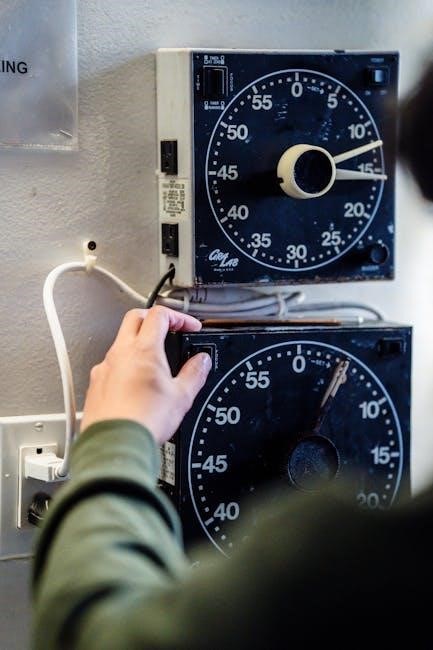
5.3 Operating the Timer and Clock
Operating the timer and clock on your GE XL44 range is simple. Set the clock by pressing the clock button and using the arrow keys to adjust the time. Once set, the clock will display the current time. To use the timer, press the timer button, set the desired minutes using the arrow keys, and press start. The timer will count down and beep when done. The timer and clock functions are essential for precise cooking. Clean the display regularly with a soft cloth to maintain visibility. Always refer to the manual for specific button functions and additional features like automatic shut-off.

Maintenance and Cleaning
Regular cleaning and maintenance ensure optimal performance. Wipe surfaces with a damp cloth and mild detergent. Avoid abrasive cleaners. Clean burner caps and grates regularly to prevent food buildup. Check and replace worn-out parts promptly. For tough stains, use a gentle scrubber. Always unplug the range before deep cleaning. Refer to the manual for specific cleaning solutions and schedules to maintain your GE XL44 range in excellent condition.
6.1 Regular Cleaning Procedures
Regular cleaning is crucial for maintaining your GE XL44 range’s performance and appearance. Clean the exterior with a damp cloth and mild detergent, avoiding abrasive cleaners. Wipe down the cooktop, burners, and grates after each use to prevent food residue buildup. For tougher stains, mix baking soda and water to create a paste, apply it, and let it sit before scrubbing. Clean the oven racks and shelves in soapy water, then rinse and dry thoroughly. Check and replace worn-out parts promptly to ensure safety and efficiency. Always unplug the range before deep cleaning to avoid accidents.
6.2 Deep Cleaning the Oven
Deep cleaning the oven of your GE XL44 range ensures optimal performance and removes stubborn grime. Turn off the power and let the oven cool completely. For continuous-clean models, run the self-cleaning cycle at 800-900°F for 2-4 hours. For standard-clean models, apply a commercial oven cleaner or a mixture of baking soda and water to interior surfaces. Let it sit overnight, then wipe away residue with a damp cloth. Avoid harsh chemicals and abrasive scrubbers to prevent damage. Regular deep cleaning maintains your oven’s efficiency and ensures a hygienic cooking environment.
6.3 Troubleshooting Common Issues
Troubleshooting common issues with your GE XL44 range starts with identifying error codes. Refer to the manual for specific code meanings, such as “F1” for control board issues or “F3” for temperature sensor problems. If the burners aren’t lighting, check the igniter and ensure the gas supply is on. For oven temperature inaccuracies, verify the sensor placement and calibration. If the range tilts, ensure the anti-tip device is properly installed. Always unplug the range before attempting repairs. For complex issues, consult the diagnostic tools section or contact GE support. Regular maintenance and timely repairs ensure your range operates efficiently and safely.
Diagnostic and Repair Information
This section provides detailed guidance on diagnosing and repairing issues with your GE XL44 range, including error code interpretation, ohmmeter tests, and part replacement procedures.
7.1 Understanding Error Codes
Understanding error codes is crucial for diagnosing issues with your GE XL44 range. The manual provides a comprehensive list of error codes, each corresponding to specific malfunctions. By identifying the error code displayed on your range, you can pinpoint the problem and take appropriate action. Common codes include those related to ignition, temperature sensors, or communication issues. Referencing the manual ensures accurate troubleshooting, helping you address minor problems before they escalate. Regular checks and adherence to the manual’s guidance can prevent errors, ensuring your range operates efficiently and safely. Always consult the manual for detailed explanations and solutions to error code alerts.
7.2 Conducting an Ohmmeter Test
Conducting an ohmmeter test on your GE XL44 range helps verify the functionality of electrical components. Ensure the range is turned off and cool before starting. Locate the component to test, such as igniter electrodes or heating elements. Set your ohmmeter to the correct scale and touch the probes to the component’s terminals. A reading of 0 ohms indicates a short circuit, while infinite resistance suggests an open circuit. For switches, test continuity by toggling the switch on and off. This test is essential for diagnosing issues like faulty igniters or malfunctioning heating elements. Always refer to the manual for specific testing procedures and interpretations.
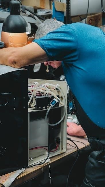
7.3 Replacing Parts and Components
Replacing parts on your GE XL44 range requires careful planning and adherence to safety guidelines. First, identify the faulty component using diagnostic tools or error codes. Turn off the power supply and allow the range to cool before starting. Use a screwdriver to access internal parts, such as igniter electrodes or burner orifices. Replace worn or damaged components with genuine GE parts, ensuring proper alignment and secure installation. Refer to the parts list in the manual for correct identification. After replacement, reconnect any wires and test the component to ensure functionality. If unsure, consult a qualified technician for assistance.

Additional Resources
For further assistance, visit the GE Appliances website to download the XL44 manual or contact GE Customer Support for personalized help. Explore online forums for user experiences and troubleshooting tips.
8.1 Downloading the GE XL44 Manual
To access the GE XL44 manual, visit the official GE Appliances website and search for your model number. Follow the prompts to download the PDF version. Ensure you select the correct model to get accurate instructions. If unavailable, check platforms like ManualsLib or Scribd for free downloads. Always verify the source for authenticity. Once downloaded, save the manual for easy reference. This document covers installation, operation, and maintenance, ensuring you maximize your appliance’s performance and safety. Refer to it regularly for troubleshooting and proper usage guidelines.
8.2 Contacting GE Customer Support
For assistance with your GE XL44 range, visit the official GE Appliances website and navigate to the support section. You can reach their customer service team at 1-800-626-2005, available Monday through Friday, 8 AM to 8 PM EST. Have your model and serial numbers ready, located on the range’s label. Registered products receive priority support. Live chat and email options are also available for convenience. Whether you need troubleshooting, repair scheduling, or general inquiries, GE’s customer support is equipped to address your concerns effectively, ensuring your appliance operates at its best.
8.3 Online Forums and Communities
Online forums and communities are valuable resources for GE XL44 users. Visit the GE Appliances Forum or platforms like ApplianceBlog to connect with other owners, share experiences, and find solutions. These forums often feature discussions on troubleshooting, maintenance tips, and repair advice from experienced users and professionals. You can also find detailed guides, diagrams, and user-shared manuals. Additionally, websites like Reddit and specialized appliance repair communities offer insights and support. Engaging with these communities can provide practical advice and help you optimize your GE XL44 range’s performance. Always verify information with official sources for accuracy.
9.1 Summary of Key Points
This manual provides a comprehensive guide for the GE XL44 range, covering safety, installation, operation, and maintenance. Key points include essential safety precautions, proper installation steps, and detailed operating instructions. Regular cleaning and deep cleaning procedures are outlined to maintain efficiency. Troubleshooting common issues and understanding error codes are also addressed. Additionally, the manual emphasizes the importance of using diagnostic tools like ohmmeter tests for repairs. By following these guidelines, users can ensure safe, efficient, and long-lasting use of their GE XL44 range. Refer to the manual for specific instructions and additional resources.
9.2 Final Tips for Optimal Use
For optimal performance, always follow the recommended cleaning schedules and maintenance routines. Regularly inspect burners and ensure proper ventilation. Use the correct cookware sizes to avoid heat loss. For even cooking, preheat the oven as instructed. Keep the anti-tip device securely installed to prevent accidents. Refer to the manual for error code interpretations and troubleshooting. Engage with online forums for shared experiences and tips. Lastly, contact GE support for any unresolved issues. By adhering to these guidelines, you’ll enjoy a safe, efficient, and long-lasting experience with your GE XL44 range.